


| Câbles BS 5308 | |||
 Câbles BS 5308
Câbles BS5308 Part 1 Type 2
PE-OS-Lead-SWA-PVC
Application
BS5308 Cable Part 1 Type 2 PE-OS-Lead-SWA-PVC are generally used when the risk of mechanical damage is
increased. The galvanised steel wire armour provides excellent protection. Generally used within industrial
process anufacturing plants for communication, data and voice transmission signals and services, Also used for
the interconnection of electrical equipment and instruments, typically in petroleum industry. They are well
adapted to underground use in industrial applications, in moist areas, where chemical and mechanical
protections are needed. The lead heath brings an enhanced resistance to aromatic hydrocarbons.
Construction
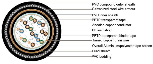
Conductor:Annealed copper, sizes: 0.5mm² and 0.75mm² mulitistranded(Class 5), 0.5 mm², 1.0 mm² solid(Class
1), 1.5mm² or 2.5mm², multistranded(Class 2) to BS6360
Insulation :PE (Polyethylene) type 03 to BS6234
Pairing :Two insulated conductors uniformly twisted together with a lay not exceeding 100mm
Colour code:See technical information
Binder tape:PETP transparent tape
Collective screen :Aluminium/polyester tape is applied over the laid up pairs metallic side down in contact with
tinned copper drain wire, 0.5mm²
Inner Sheath:PVC (polyvinyl chloride), type TM 1 or type 6 toBS 6746
Lead Sheath :Lead Alloy
Bedding :PVC (polyvinyl chloride), TM 1 to BS 6746
Amour :Galvanized steel wire armour
Outer sheath:PVC Sheath, type TM 1 or type 6 to BS 6746
Sheath colour :Black or blue
Caractéristiques Mécaniques et Électriques
Température de fonctionnement:-40°C à +70°C (installation fixe)
/ 0°C à +50°C (en fonctionnement)
Rayon de courbure minimal:15 fois le diamètre total
| Taille de la section du conducteur (mm²) | mm2 | 0.5 | 0.5 | 0.75 | 1.0 | 1.5 | |
|---|---|---|---|---|---|---|---|
| Composition du conducteur (n° x mm) | No. x mm | 1 x 0.8 | 16 x 0.2 | 24 x 0.2 | 1 x 1.13 | 7 x 0.53 | |
| Résistance maximale (Ω/km) | ohm/km | 36.8 | 39.7 | 26.5 | 18.2 | 12.3 | |
| Résistance d'isolation minimale (GΩ/km) | Gohm/km | 5 | 5 | 5 | 5 | 5 | |
| Capacité déséquilibre à 1 kHz (pF/250m) | pF/250m | 250 | |||||
| Capacité mutuelle maximale (pF/m) | pF/m | 75 | 75 | 75 | 75 | 85 | |
| Capacité mutuelle maximale à 1 kHz pour câbles IS/OS (y compris 1 paire et 2 paires) | pF/m | 115 | 115 | 115 | 115 | 120 | |
| Rapport L/R maximal (μH/Ω) | μH/ohm | 25 | 25 | 25 | 25 | 40 | |
| Tension de test | Noyau à noyau | V | 1000 | 1000 | 1000 | 1000 | 1000 |
| Noyau à écran | V | 1000 | 1000 | 1000 | 1000 | 1000 | |
| Tension nominale maximale (V) | V | 300/500 | 300/500 | 300/500 | 300/500 | 300/500 | |
Nombre de paires |
Nombre et diamètre des fils |
Section nominale du conducteur |
Épaisseur nominale de l'isolation |
Diamètre nominal au-dessus du lit |
Épaisseur nominale de l'armure | Diamètre nominal du cable |
Poids approximatif |
|---|---|---|---|---|---|---|---|
| no./mm | mm2 | mm | mm | mm | mm | kg/km | |
| 1 | 1/0.80 | 0.5 | 0.5 | 6.3 | 0.9 | 10.7 | 200 |
| 2 | 1/0.80 | 0.5 | 0.5 | 7.1 | 0.9 | 11.5 | 260 |
| 5 | 1/0.80 | 0.5 | 0.5 | 11.6 | 0.9 | 16.2 | 460 |
| 10 | 1/0.80 | 0.5 | 0.5 | 15 | 1.25 | 20.7 | 790 |
| 15 | 1/0.80 | 0.5 | 0.5 | 17.1 | 1.25 | 22.8 | 1100 |
| 20 | 1/0.80 | 0.5 | 0.5 | 19.4 | 1.6 | 26 | 1280 |
| 30 | 1/0.80 | 0.5 | 0.5 | 23 | 1.6 | 29.8 | 1520 |
| 50 | 1/0.80 | 0.5 | 0.5 | 28.9 | 1.6 | 26.1 | 2100 |
| 1 | 16/0.20 | 0.5 | 0.6 | 7 | 0.9 | 11.4 | 250 |
| 2 | 16/0.20 | 0.5 | 0.6 | 7.9 | 0.9 | 12.3 | 300 |
| 5 | 16/0.20 | 0.5 | 0.6 | 13.1 | 0.9 | 17.9 | 560 |
| 10 | 16/0.20 | 0.5 | 0.6 | 17.2 | 1.25 | 22.9 | 970 |
| 15 | 16/0.20 | 0.5 | 0.6 | 19.8 | 1.6 | 26.4 | 1240 |
| 20 | 16/0.20 | 0.5 | 0.6 | 22.3 | 1.6 | 29.1 | 1640 |
| 30 | 16/0.20 | 0.5 | 0.6 | 26.9 | 1.6 | 33.9 | 1770 |
| 50 | 16/0.20 | 0.5 | 0.6 | 33.9 | 2 | 42.1 | 2770 |
| 1 | 1/1.13 | 1 | 0.6 | 7.4 | 0.9 | 11.8 | 290 |
| 2 | 1/1.13 | 1 | 0.6 | 8.4 | 0.9 | 13 | 345 |
| 5 | 1/1.13 | 1 | 0.6 | 14.2 | 1.25 | 19.7 | 790 |
| 10 | 1/1.13 | 1 | 0.6 | 17.4 | 1.25 | 24.3 | 1310 |
| 15 | 1/1.13 | 1 | 0.6 | 21.3 | 1.6 | 28.1 | 1740 |
| 20 | 1/1.13 | 1 | 0.6 | 24.4 | 1.6 | 31.2 | 2040 |
| 30 | 1/1.13 | 1 | 0.6 | 29 | 1.6 | 36.2 | 2180 |
| 50 | 1/1.13 | 1 | 0.6 | 37.3 | 2 | 45.7 | 3500 |
| 1 | 7/0.53 | 1.5 | 0.6 | 8.3 | 0.9 | 12.9 | 320 |
| 2 | 7/0.53 | 1.5 | 0.6 | 9.7 | 0.9 | 14.3 | 420 |
| 5 | 7/0.53 | 1.5 | 0.6 | 16.4 | 1.25 | 22.1 | 940 |
| 10 | 7/0.53 | 1.5 | 0.6 | 21.6 | 1.6 | 28.4 | 1500 |
| 15 | 7/0.53 | 1.5 | 0.6 | 25.2 | 1.6 | 32.2 | 1970 |
| 20 | 7/0.53 | 1.5 | 0.6 | 28.5 | 2 | 36.5 | 2400 |
| 30 | 7/0.53 | 1.5 | 0.6 | 34.3 | 2 | 42.5 | 3170 |
| 50 | 7/0.53 | 1.5 | 0.6 | 43.6 | 2.5 | 53.4 | 5020 |