| IEC 60502-1 Cables | |||
| 600/1000V, PVC Insulated Cables | 600/1000V, XLPE Insulated Cables |
 IEC 60502-1 Cables
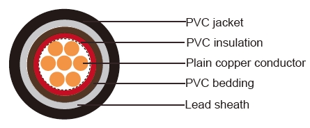
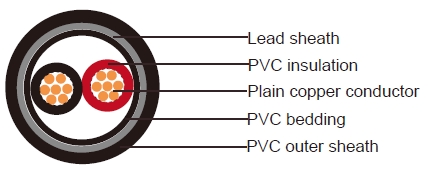
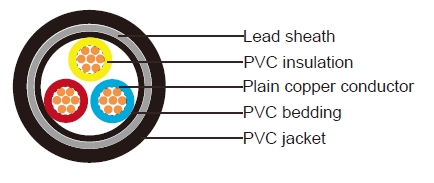
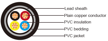
600/1000V, PVC Insulated and Lead Sheathed Cables according to IEC 60502-1(unarmoured)
Application
IEC 60502-1 cables are used for electricity supply in low voltage installation system, IEC 60502-1 cables are
suitable for installation in indoors and outdoors, in cable ducts, under ground, in power and switching stations,
local energy distributions, industrial plants, where there is no risk of mechanical damage. The lead sheath brings
an enhanced resistance to aromatic hydrocarbons.
Construction
Conductors
The conductors shall be either of Class 1 or Class 2 of plain or metal-coated annealed copper or of plain
aluminium or aluminium alloy, or of Class 5 of plain or metal-coated copper in accordance with IEC 60228.
Insulation
PVC Insulation material and thickness shall be as per IEC 60502-1, PVC material shall be Type A as per IEC
60502-1.
Colour Code
Colour Code (1) :
1Core: Red or Black
Colour Code (2) :
1Core: Brown or Blue
Other colours can be manufactured upon request.
Assembly/Inner Covering
The inner coverings may be extruded or lapped. For cables with circular cores, except cables with more than five
cores, a lapped inner covering shall be permitted only if the interstices between the cores are substantially filled.
A suitable binder is permitted before application of an extruded inner covering. The materials used for inner
coverings and fillers shall be suitable for the operating temperature of the cable and compatible with the
insulating material.For halogen free cables, the inner covering and fillers shall also be halogen free compound.
Lead Sheath
lead or lead alloy and shall be applied as a reasonably tight-fitting seamless tube.
Outer Sheath
Outer sheath shall be of extruded PVC Type ST1/ST2 as per IEC 60502-1, Polyethylene type ST3/ST7, Halogen
free compound ST8, Polychloroprene, chlorosulfonated polyethylene or similar polymers, type SE1 are also
available on request.
Cable Parameters:
Single core(unarmoured)

| Nominal Cross Section | Diameter of Conductor (Approx.) | Nominal Insulation Thickness | Nominal Inner Covering Thickness | Nominal Lead Sheath Thickness | Nominal Sheath Thickness | Overall Diameter (Approx.) |
|---|---|---|---|---|---|---|
| mm² | mm | mm | mm | mm | mm | mm |
| 1x10 | 3.6 | 1 | 1 | 1.2 | 1.4 | 12.8 |
| 1x16 | 4.5 | 1 | 1 | 1.2 | 1.4 | 13.7 |
| 1x25 | 5.6 | 1.2 | 1 | 1.2 | 1.4 | 15.3 |
| 1x35 | 6.7 | 1.2 | 1 | 1.2 | 1.5 | 16.4 |
| 1x50 | 8 | 1.4 | 1 | 1.2 | 1.5 | 18.3 |
| 1x70 | 9.4 | 1.4 | 1 | 1.2 | 1.6 | 19.8 |
| 1x95 | 11 | 1.6 | 1 | 1.3 | 1.7 | 22.1 |
| 1x120 | 12.4 | 1.6 | 1 | 1.3 | 1.7 | 23.7 |
| 1x150 | 13.8 | 1.8 | 1 | 1.4 | 1.8 | 25.7 |
| 1x185 | 15.3 | 2 | 1 | 1.4 | 1.8 | 27.9 |
| 1x240 | 17.5 | 2.2 | 1 | 1.5 | 1.9 | 30.8 |
| 1x300 | 19.5 | 2.4 | 1 | 1.6 | 2 | 33.5 |
| 1x400 | 22.6 | 2.6 | 1.2 | 1.7 | 2.2 | 38 |
| 1x500 | 25.2 | 2.8 | 1.2 | 1.8 | 2.3 | 41.4 |
| 1x630 | 28.3 | 2.8 | 1.2 | 1.9 | 2.4 | 44.9 |
Two cores(unarmoured)

| Nominal Cross Section | Diameter of Conductor (Approx.) | Nominal Insulation Thickness | Nominal Inner Covering Thickness | Nominal Lead Sheath Thickness | Nominal Sheath Thickness | Overall Diameter (Approx.) |
|---|---|---|---|---|---|---|
| mm² | mm | mm | mm | mm | mm | mm |
| 2x2.5 | 1.8 | 0.8 | 1 | 1.2 | 1.8 | 14.8 |
| 2x4 | 2.3 | 1 | 1 | 1.2 | 1.8 | 16.6 |
| 2x6 | 2.8 | 1 | 1 | 1.2 | 1.8 | 17.6 |
| 2x10 | 3.6 | 1 | 1 | 1.2 | 1.8 | 19.2 |
| 2x16 | 4.5 | 1 | 1 | 1.2 | 1.8 | 21 |
| 2x25 | 5.6 | 1.2 | 1 | 1.2 | 1.8 | 24.1 |
| 2x35 | 6.7 | 1.2 | 1 | 1.3 | 1.8 | 26.4 |
| 2x50 | 8 | 1.4 | 1 | 1.4 | 1.9 | 30.3 |
| 2x70 | 9.4 | 1.4 | 1 | 1.5 | 2 | 33.4 |
| 2x95 | 11 | 1.6 | 1.2 | 1.6 | 2.2 | 38.4 |
| 2x120 | 12.4 | 1.6 | 1.2 | 1.7 | 2.3 | 41.6 |
| 2x150 | 13.8 | 1.8 | 1.2 | 1.8 | 2.4 | 45.7 |
| 2x185 | 15.3 | 2 | 1.4 | 1.9 | 2.6 | 50.5 |
| 2x240 | 17.5 | 2.2 | 1.4 | 2.1 | 2.8 | 56.4 |
| 2x300 | 19.5 | 2.4 | 1.6 | 2.3 | 3 | 62.2 |
Three cores(unarmoured)

| Nominal Cross Section | Diameter of Conductor (Approx.) | Nominal Insulation Thickness | Nominal Inner Covering Thickness | Nominal Lead Sheath Thickness | Nominal Sheath Thickness | Overall Diameter (Approx.) |
|---|---|---|---|---|---|---|
| mm² | mm | mm | mm | mm | mm | mm |
| 3x1.5 | 1.4 | 0.8 | 1 | 1.2 | 1.8 | 14.5 |
| 3x2.5 | 1.8 | 0.8 | 1 | 1.2 | 1.8 | 15.3 |
| 3x4 | 2.3 | 1 | 1 | 1.2 | 1.8 | 17.3 |
| 3x6 | 2.8 | 1 | 1 | 1.2 | 1.8 | 18.3 |
| 3x10 | 3.6 | 1 | 1 | 1.2 | 1.8 | 20.1 |
| 3x16 | 4.5 | 1 | 1 | 1.2 | 1.8 | 22 |
| 3x25 | 5.6 | 1.2 | 1 | 1.3 | 1.8 | 25.4 |
| 3x35 | 6.7 | 1.2 | 1 | 1.3 | 1.9 | 28 |
| 3x50 | 8 | 1.4 | 1 | 1.5 | 2 | 32.2 |
| 3x70 | 9.4 | 1.4 | 1.2 | 1.6 | 2.1 | 36 |
| 3x95 | 11 | 1.6 | 1.2 | 1.7 | 2.3 | 40.9 |
| 3x120 | 12.4 | 1.6 | 1.2 | 1.8 | 2.4 | 44.3 |
| 3x150 | 13.8 | 1.8 | 1.4 | 1.9 | 2.5 | 49.2 |
| 3x185 | 15.3 | 2 | 1.4 | 2 | 2.7 | 53.8 |
| 3x240 | 17.5 | 2.2 | 1.6 | 2.2 | 2.9 | 60.6 |
| 3x300 | 19.5 | 2.4 | 1.6 | 2.4 | 3.1 | 66.5 |
Four cores(unarmoured)

| Nominal Cross Section | Diameter of Conductor (Approx.) | Nominal Insulation Thickness | Nominal Inner Covering Thickness | Nominal Lead Sheath Thickness | Nominal Sheath Thickness | Overall Diameter (Approx.) |
|---|---|---|---|---|---|---|
| mm² | mm | mm | mm | mm | mm | mm |
| 4x1.5 | 1.4 | 1 | 1 | 1.2 | 1.8 | 15.2 |
| 4x2.5 | 1.8 | 1 | 1 | 1.2 | 1.8 | 16.2 |
| 4x4 | 2.3 | 1 | 1 | 1.2 | 1.8 | 18.4 |
| 4x6 | 2.8 | 1 | 1 | 1.2 | 1.8 | 19.6 |
| 4x10 | 3.6 | 1 | 1 | 1.2 | 1.8 | 21.5 |
| 4x16 | 4.5 | 1 | 1 | 1.2 | 1.8 | 23.8 |
| 4x25 | 5.6 | 1 | 1 | 1.3 | 1.8 | 27.7 |
| 4x35 | 6.7 | 1 | 1 | 1.4 | 1.9 | 30.7 |
| 4x50 | 8 | 1.2 | 1.2 | 1.6 | 2.1 | 35.8 |
| 4x70 | 9.4 | 1.2 | 1.2 | 1.7 | 2.2 | 39.6 |
| 4x95 | 11 | 1.2 | 1.2 | 1.8 | 2.4 | 45.1 |
| 4x120 | 12.4 | 1.4 | 1.4 | 1.9 | 2.6 | 49.4 |
| 4x150 | 13.8 | 1.4 | 1.4 | 2 | 2.7 | 54.3 |
| 4x185 | 15.3 | 1.6 | 1.6 | 2.2 | 2.9 | 60 |
| 4x240 | 17.5 | 1.6 | 1.6 | 2.4 | 3.1 | 67.1 |
| 4x300 | 19.5 | 1.6 | 1.6 | 2.6 | 3.3 | 73.7 |


