|
Industrial Cables-British Standard
Coil End Lead Cable to BS 6195
Application and Description:
Coil End Lead Cable to BS 6195 cables are designed as power leads for permanent connection to coil winding motors, panel wiring and electrical machinery. Coil End Lead Cable to BS 6195 cables are able to withstand high temperature and immersion in varnish. Other applications include vehicle wiring, The HOFR sheath resists oil and varnish and the stranding is designed as a compromise between flexibility and positional stability. Also Coil End Lead Cable to BS 6195 cables are suitable for use as an alternative to tri-rated and bi-rated cable in certain applications.
Cable Construction:


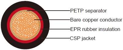
Fine bare copper strands
Stranding to BS 6360 CL-5 or IEC 60228 CL-5
PETP(Polyethylene Terephthalate) tape separator
EPR-HOFR( Ethylene Propylene Rubber-Heat and Oil Resistant and Flame Retardant) insulation, type FR1 (for
type 4A & 4C) & type FR2 (for type 4D & 4E&4F) to BS 7655-1.5, type EI2 (for type 5) to EN 50363-1
CSP(Chlorosulphonated Polyethylene), HOFR (Heat and Oil Resistant and Flame Retardant) sheath to BS 6899, black
Technical Characteristics:
Working voltage:
Type A: 300/500V
Type C: 600/1000V
Type D: 1900/3300V
Type E: 3800/6600V
Type F: 6350/11000V
Minimum bending radius: 4xOverall diameter
Operating temperature max. : +90º C(for type 4), +180º C(for type 5)
Cable Parameter:
| AWG (No of Strands/ Strand Diameter) |
No. of Cores x Nominal Cross Sectional Area #xmm² |
Nominal Thickness of Insulation mm | Nominal Overall Diameter mm |
Nominal Weight kg/km |
|---|---|---|---|---|
| TYPE A | ||||
| 18(24/32) | 1x0.75 | 0.8 | 3.5 | 16 |
| 17(32/32) | 1x1 | 0.8 | 3.7 | 19 |
| 16(30/30) | 1x1.5 | 0.8 | 4 | 25 |
| 14(50/30) | 1x2.5 | 0.9 | 4.6 | 37 |
| 12(56/28) | 1x4 | 1 | 5.4 | 57 |
| 10(84/28) | 1x6 | 1 | 6.5 | 80 |
| 8(80/26) | 1x10 | 1.2 | 7.9 | 130 |
| TYPE C | ||||
| 20(16/32) | 1x0.5 | 1.4 | 4.5 | 17 |
| 18(24/32) | 1x0.75 | 1.4 | 4.7 | 21 |
| 17(32/32) | 1x1 | 1.4 | 4.9 | 24 |
| 16(30/30) | 1x1.5 | 1.4 | 5.2 | 30 |
| 14(50/30) | 1x2.5 | 1.4 | 5.6 | 41 |
| 12(56/28) | 1x4 | 1.4 | 6.3 | 66 |
| 10(84/28) | 1x6 | 1.5 | 7.5 | 93 |
| 8(80/26) | 1x10 | 1.5 | 8.5 | 136 |
| 6(128/26) | 1x16 | 1.5 | 9.6 | 206 |
| 4(200/26) | 1x25 | 1.6 | 11.4 | 300 |
| 2(280/26) | 1x35 | 1.6 | 12.8 | 406 |
| 1(400/26) | 1x50 | 1.7 | 14.8 | 573 |
| 2/0(356/24) | 1x70 | 1.8 | 17.2 | 793 |
| 3/0(485/24) | 1x95 | 2 | 19.7 | 1028 |
| 4/0(614/24) | 1x120 | 2.2 | 21.9 | 1285 |
| 300 MCM (765/24) | 1x150 | 2.3 | 24.1 | 1562 |
| 350 MCM (944/24) | 1x185 | 2.4 | 26.3 | 1914 |
| 500MCM(1225/24) | 1x240 | 2.4 | 28.3 | 2431 |
| (1525/24) | 1x300 | 2.6 | 33 | 3024 |
| (2013/24) | 1x400 | 2.8 | 37.4 | 3948 |
| TYPE D | ||||
| 6(128/26) | 1x16 | 2.8 | 12.4 | 255 |
| 4(200/26) | 1x25 | 2.8 | 13.8 | 351 |
| 2(280/26) | 1x35 | 2.8 | 15.2 | 458 |
| AWG (No of Strands/ Strand Diameter) |
No. of Cores x Nominal Cross Sectional Area #xmm² |
Nominal Thickness of Insulation mm | Nominal Overall Diameter mm |
Nominal Weight kg/km |
|---|---|---|---|---|
| 1(400/26) | 1x50 | 2.8 | 17.1 | 616 |
| 2/0(356/24) | 1x70 | 2.8 | 19.2 | 820 |
| 3/0(485/24) | 1x95 | 3 | 22 | 1097 |
| 4/0(614/24) | 1x120 | 3 | 23.5 | 1340 |
| 300 MCM (765/24) | 1x150 | 3 | 25.5 | 1635 |
| 350 MCM (944/24) | 1x185 | 3 | 27.5 | 1973 |
| 500MCM(1225/24) | 1x240 | 3 | 30.6 | 2504 |
| (1525/24) | 1x300 | 3 | 33.8 | 3098 |
| (2013/24) | 1x400 | 3 | 37.8 | 4045 |
| TYPE E | ||||
| 6(128/26) | 1x16 | 5 | 17.2 | 384 |
| 4(200/26) | 1x25 | 5 | 18.6 | 495 |
| 2(280/26) | 1x35 | 5 | 20 | 613 |
| 1(400/26) | 1x50 | 5 | 22.1 | 796 |
| 2/0(356/24) | 1x70 | 5 | 24.2 | 1020 |
| 3/0(485/24) | 1x95 | 5 | 26.3 | 1287 |
| 4/0(614/24) | 1x120 | 5 | 27.8 | 1542 |
| 300 MCM (765/24) | 1x150 | 5 | 29.8 | 1853 |
| 350 MCM (944/24) | 1x185 | 5 | 32.1 | 2225 |
| 500MCM(1225/24) | 1x240 | 5 | 35.1 | 2782 |
| TYPE F | ||||
| 6(128/26) | 1x16 | 7.6 | 22.9 | 566 |
| 4(200/26) | 1x25 | 7.6 | 24.1 | 680 |
| 2(280/26) | 1x35 | 7.6 | 25.5 | 810 |
| 1(400/26) | 1x50 | 7.6 | 27.3 | 997 |
| 2/0(356/24) | 1x70 | 7.6 | 29.4 | 1237 |
| 3/0(485/24) | 1x95 | 7.6 | 31.5 | 1520 |
| 4/0(614/24) | 1x120 | 7.6 | 33.3 | 1804 |
| 300 MCM (765/24) | 1x150 | 7.6 | 35.3 | 2131 |
| 350 MCM (944/24) | 1x185 | 7.6 | 37.3 | 2503 |
| 500MCM(1225/24) | 1x240 | 7.6 | 40.3 | 3081 |
